2005
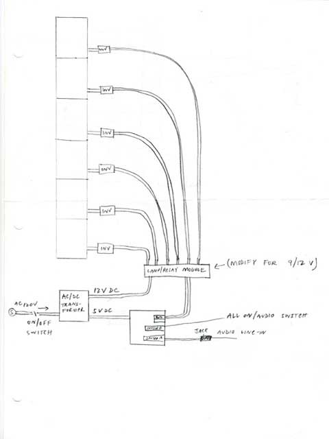
Seven surplus cold cathode lamps from defunct laptops are wired in parallel and connected to an audio to direct current voltage controller.
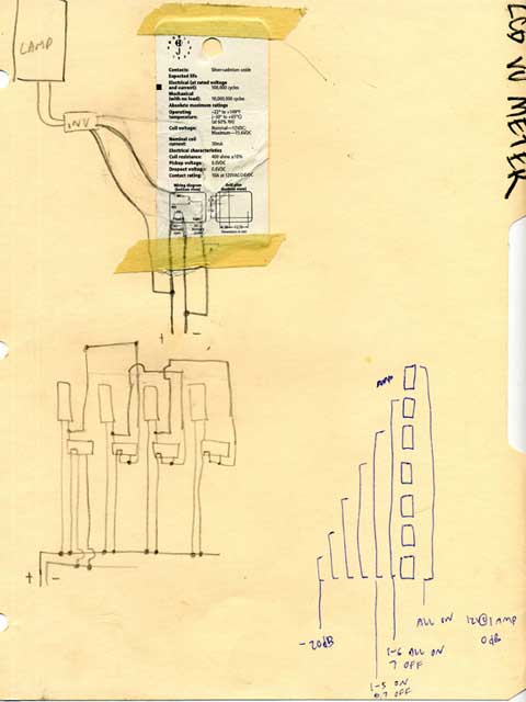
Two versions going right now, digital and analog. The audio is definitely more responsive on the analog version, except the relays opening the circuit to the lamps is little noisy. The relays are also greatly stressed, due to being constantly modulated by the erratic changing of the music, so I am probably going to reach their life cycle too quickly. The digital one, always needs tweaking. The analog one is easier to maintain and adjust to frequency response, while the digital one is a pain in the ass to tweak.
The other problem is, it's probably not good for the small fluorescent tube to be driven so erratically. I left the lamp on for quite some time, a ten hour run, and all seven lamps haven't failed yet. I have found that if the inverters are driven to hard, they give off spurious RF. I only know this because I tested it next to a TV antennae. So I have to either better shield the inverters, lower the voltage incoming to the inverter, or just have fun controlling the fuzz on my TV with music.
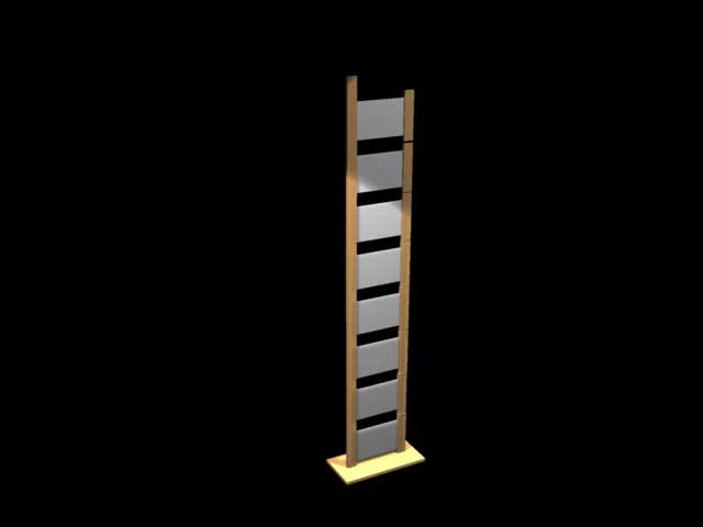
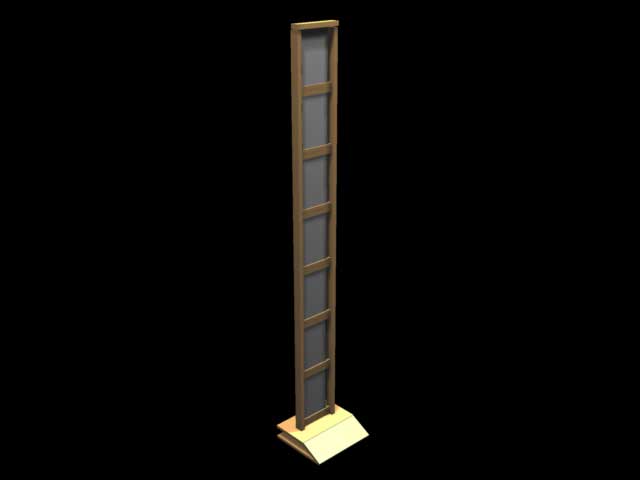
renders
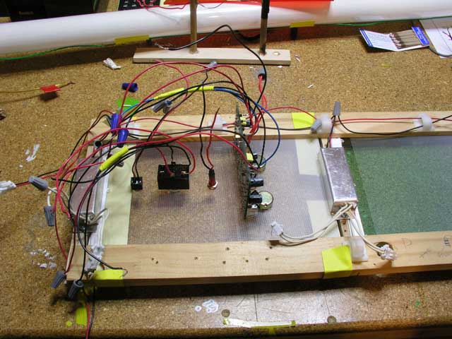
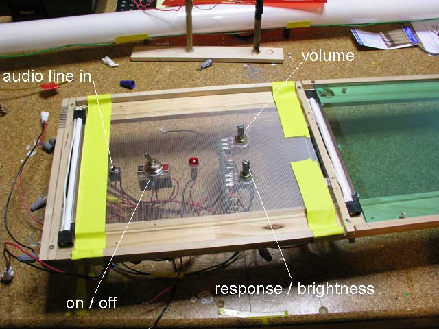
circuitry
parts
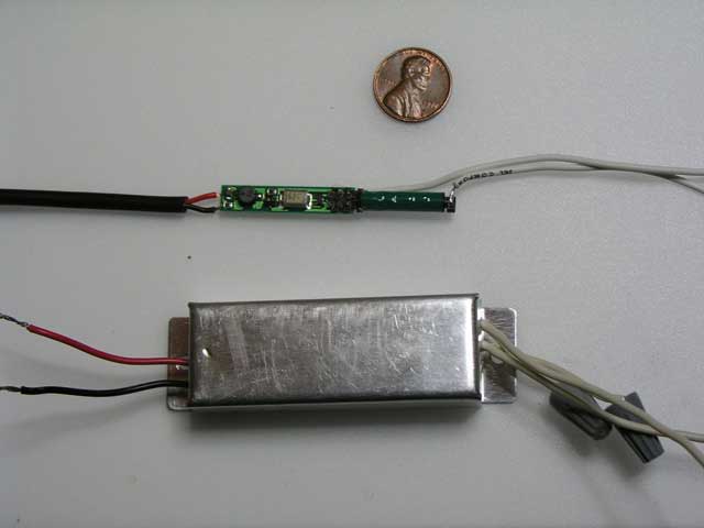
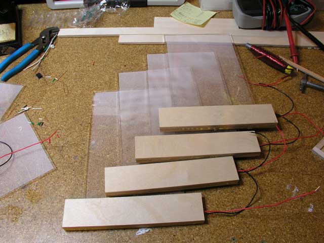
Here is a side by side comparison of the two inverters I tested. The one on the bottom I have used for a while and it can drive a fairly large tube, and it's duty. The top one is about five dollars more, but the footprint is sooo much smaller.
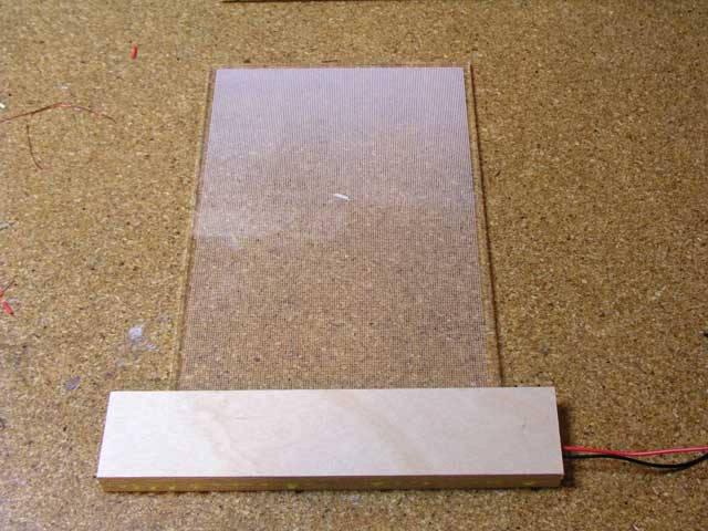
One of my main concerns with the lamp is trying to make it as slim as possible, and this inverter allows me to shave almost 3/4 of an inch off the overall width of the frame out.
Both inverters can operate off 12 Volts DC, and can go as low 6 Volts DC. The smaller inverter outputs ~800 Volts. I don't know what the larger one can do, it never came with a spec sheet, but I am guessing it can top out at ~1200 Volts, I drove a four foot tube with it.
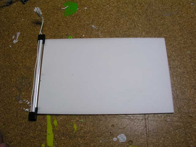
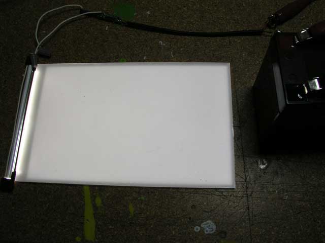
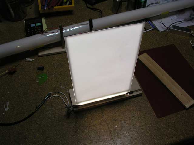
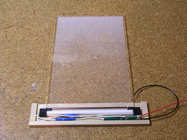
Here is the cold cathode fluorescent back-light from a never produced laptop. These things are great, nice even light, slim form factor, easy to hook up.
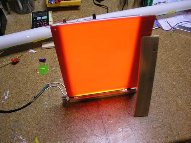
color tests
purdy red!
mockup
wooden case
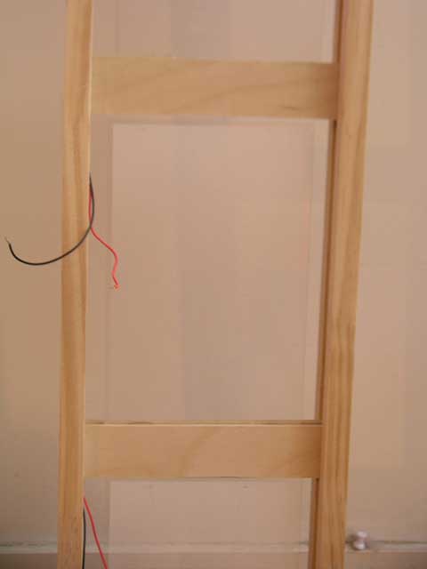
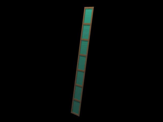
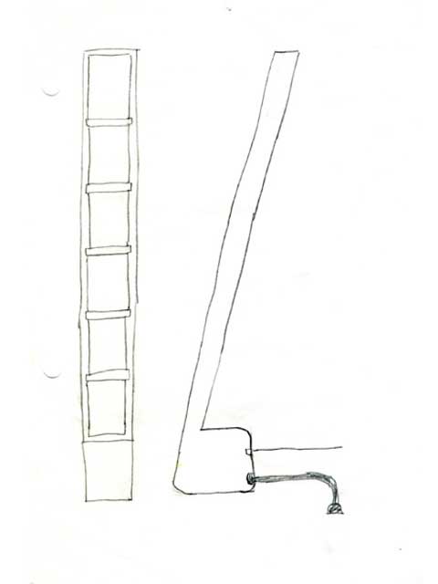
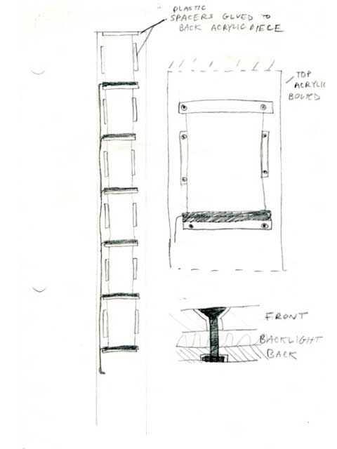
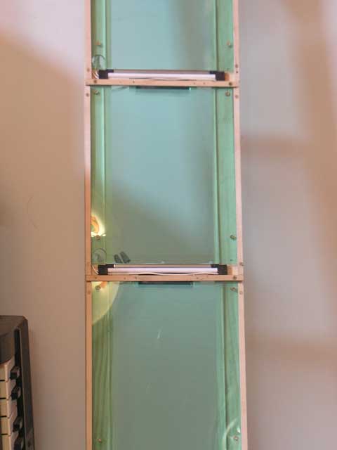
After reworking this lamp with the new inverters, it gave me the opportunity to make the entire lamp thinner. I then began to think of it being a slotted system, where the individual lamps could somehow be slotted into a structure, pre-wired.
I wanted to make contact points for power to the lamps on the individual wooden slats, but for now I just wired them out. Looking good, just gotta sand'em. The physical slat could be smaller, but I think they are in a good proportion for a hand to hold one.
two L293DDs
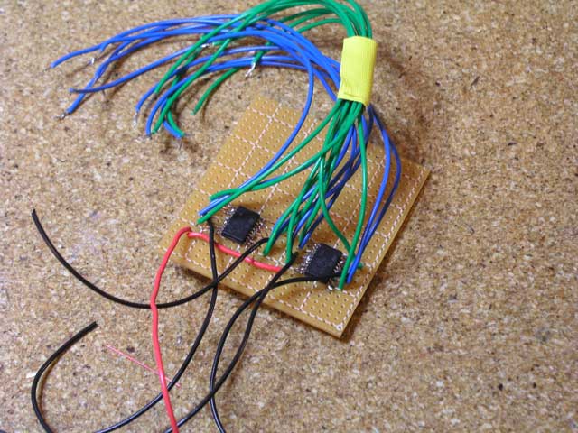
These are push pull drivers capable of using a 5 volt logic signal to control heavy current devices, like solenoids, motors, etc. Each chip controls four outputs, with a peak output current of 1.2 amps. I needed eight outputs, so here you see two.
Wiring outputs and inputs for the stamp, green are wired to the pins of the stamp, and the blue correspond to the outputs, and are connected to whatever I am driving. I didn't realize, until I received the chips in the mail, that I had ordered surface mount chips, so you could call me a DIP sh*t.
My etching skills are horrible, so the jumpers have to do for now.
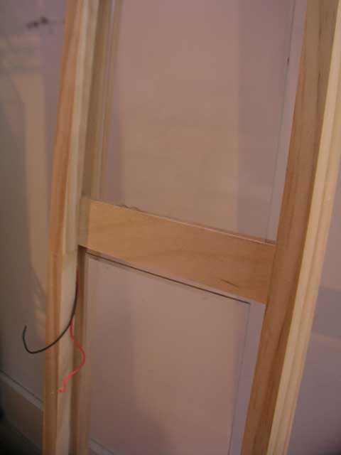
frame out