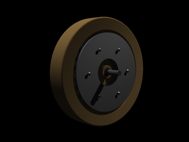
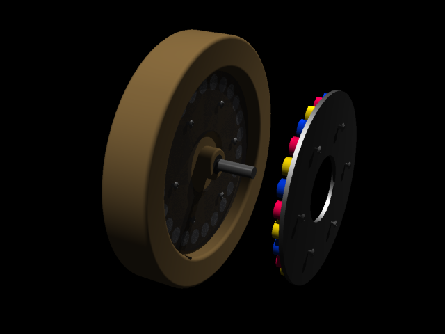
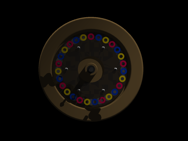
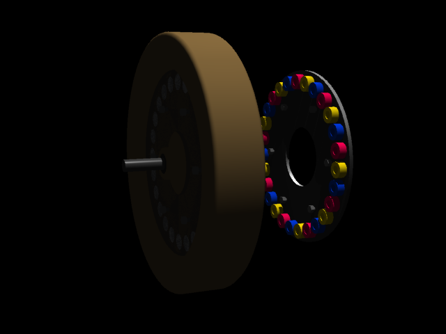
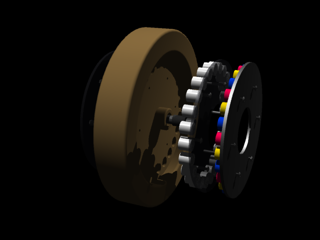
axial flux permanent magnet generator / motor
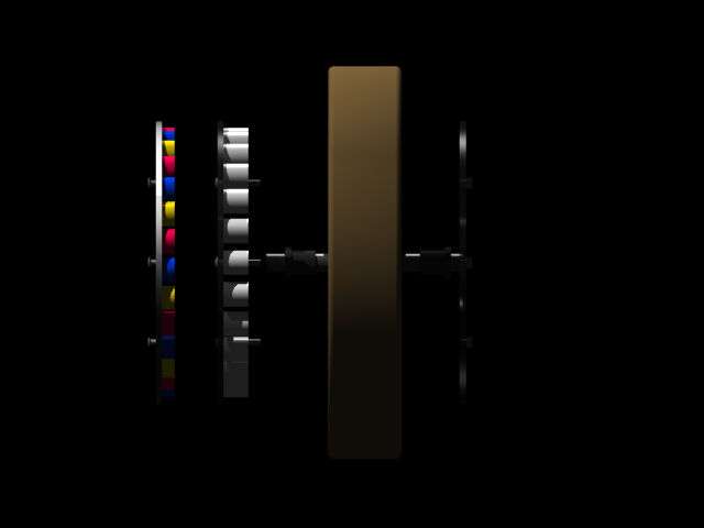
This is a single sided core less axial flux motor with non-overlap windings for easy assembly and disassembly. This model has 24 permanent magnets and 27 coils. This design is based on similar designs for wind generators, yet is geared more toward an in-wheel motor application. As with most generators, motors, alternators, etc., there are a plethora of topologies for a variety of applications. I have not built this model yet, so I have no idea of its performance.
A good technical reference book about everything axial flux is "Axial Flux Permanent Magnet Brushless Machines" by Jacek F. Gieras, although a little pricey. This book is very helpful if you plan on building your own motor or generator in a similar fashion.
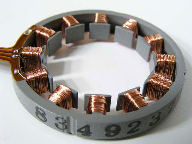
Gramme ring stator
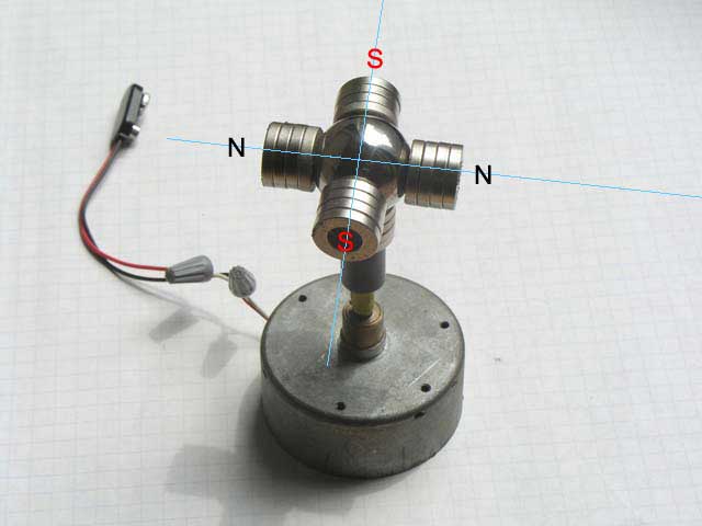
super simple alternator
A steel ball and some magnets are arranged appropriately atop a a small brushed DC motor. Just add coils.
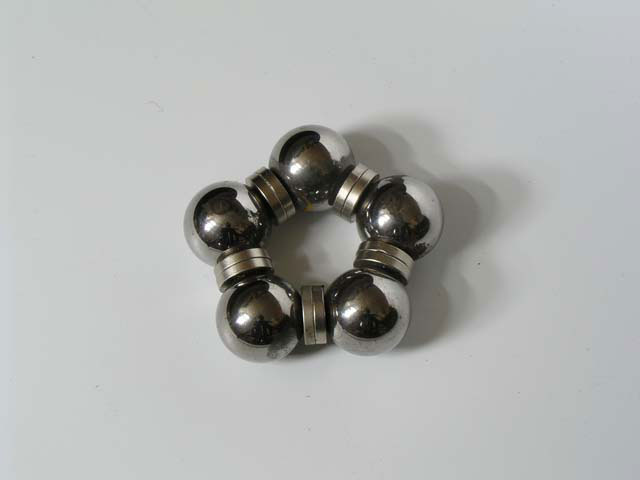
magnets
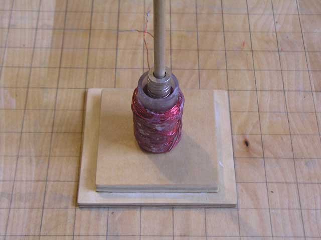
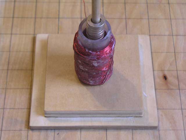
some various wound coils
hard drive stator
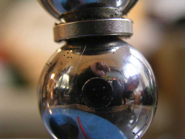
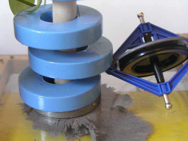
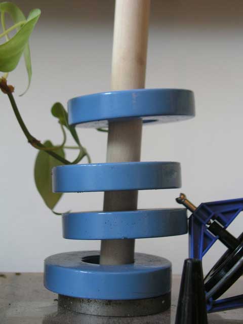
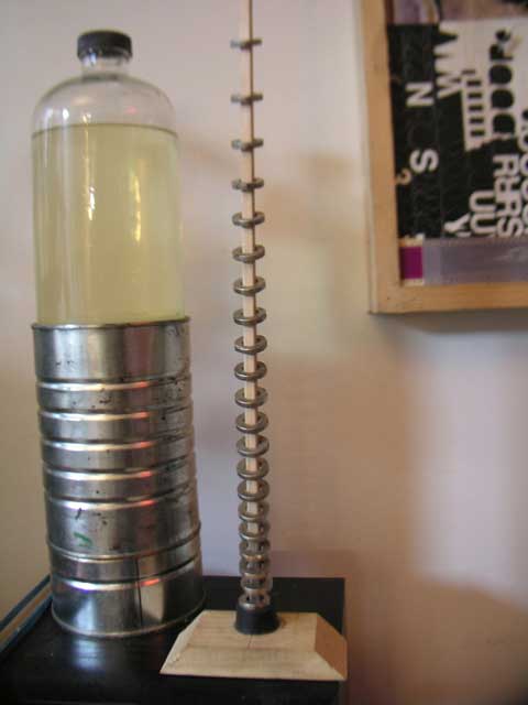
pulser
Similar in the physical design configuration of a Tesla coil, yet instead of a secondary coil, a free floating dual magnetic core is used, more like a gauss gun. The two magnetic cores sit atop each other polar opposed. In principle, this is somewhat like speaker without a diaphragm. This arrangement helped me understand the underlying principles at work in the inductive properties of a Tesla coil, yet without the tank circuit, high voltage and high frequency.

When the coil is pulsed, the top magnetic core is ejected and falls. When the pulses are timed accordingly, the top magnetic core can achieve higher distances.
UHF transmitter
- CHANNEL: 19
- BAND: 500-506
- CENTER FREQUENCY: 503
- VIDEO CARRIER: 501.25 MHz
- COLOR CARRIER: 504.83 MHz
- SOUND CARRIER: 505.75 MHz
These are the rewired guts of a video transmitter. I found that the original wiring of this thing was schlocky, so I went and made some improvements. Shielding the RF wires improved the clarity of the transmitted picture.
This is an old e-bayyed Casio portable LCD television with the controls rewired. Now it runs on 12V DC. I've been using this as a range tester.
Finished component box. Now I can hop frequencies faster and more easily with the larger knobs on the pots.
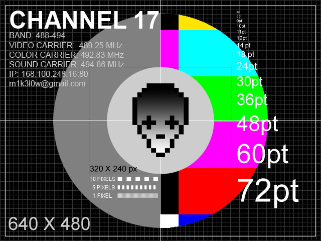
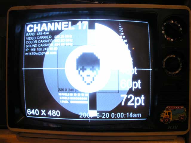
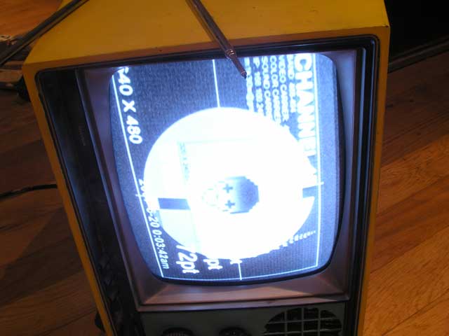
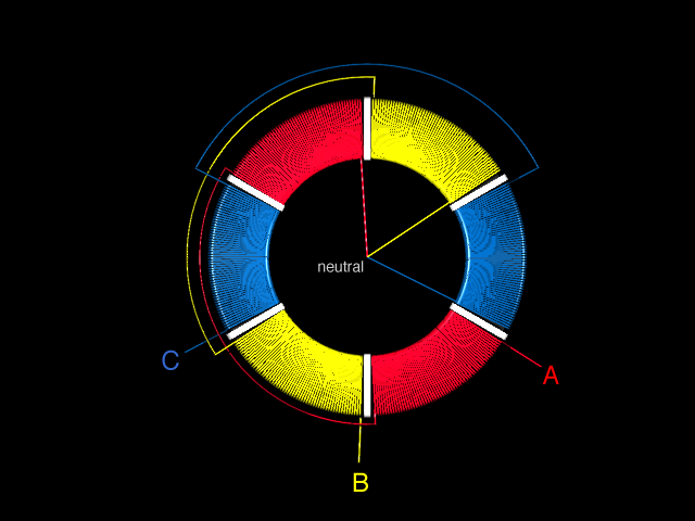
Here is a test pattern I did up for the low power UHF station. I used to be on channel 19, but moved down to 17 due to some interference. On testing the range, the analog UHF tuners pick up the signal pretty good at twenty feet. Yet with a digital tuner I have tested, it just can't get a good grip on the signal, probably because the frequency and phase are not in step with the color carrier. The audio signal is carrying well on both the analog and digital tuners.
A good book for reference on television servicing for older cathode tube sets is "Color and Black and White Television Theory and Servicing" by Alvin A. Liff and J.A. Sam Wilson, CET. ISBN 0-13-150012-0
transformer stethoscope
This is a very simple tool to diagnose or listen to transformers. Basically it is just a pickup, without the magnet. I made a simple coil and wired it directly to a set of headphones. Take the left and right speaker's positive wires and wire them to one end of the coil, and then take the ground wires of the speakers and wire them to the other end of the coil.
I wrapped some 18 AWG wire around an acrylic cylinder, formed two layers, then epoxied the whole thing in place. I built one so a typical wall wort style transformer could fit inside the coil. Now I can couple my ear drum anvils directly to AC!
It might make a nice instrument. You could have arrays of surge protectors plugged to the max with transformers and then wave the "stethoscope" over the array producing all different types of hum. You could run the "stethoscope" into an amp and have all types of fun.
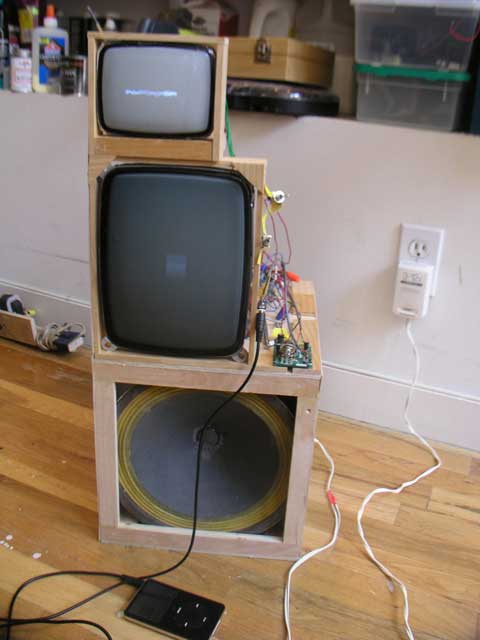
oscillo-speaker
I did a really sloppy job on this thing, but I just wanted to test it out before I made a nice version.
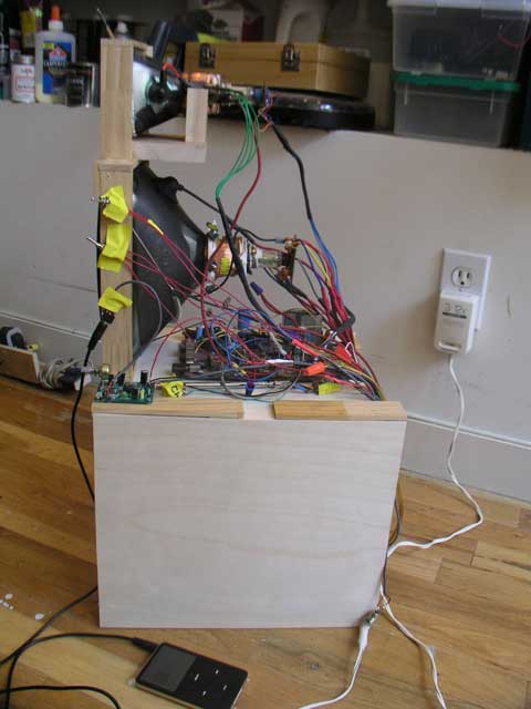
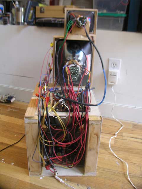
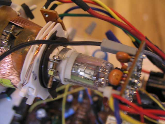
Two cathode tubes, an op amp, and a speaker are re-wired for visual musical display. The deflection coils around the two tubes are re-wired as audio inputs. I did a really messy job on wiring this thing, but hey, I am going to encase it anyway.
This sort of re-wiring has also been known as Wobble-vision. It's a mega cheap solution for an oscilloscope. Newer televisions and monitors usually will not allow you to do this conversion, due to all the digital circuitry. If the television is black and white, you can pretty much bet the re-wiring will work. With all the old tubes being replaced by flat screens, you are more than likely to see one on the curb.
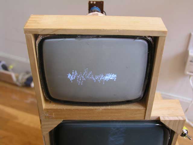
I re-wired the deflection coils of the two tubes differently, so as to give me two different waveform displays. The op-amp allowed me to amplify a line level audio signal so as to more effectively drive the speaker and deflection coils as well have a volume control.
really bad ascii diagrams and instructions
Listening to radio signals on this thing is great because I can more easily see patterns on certain frequencies. It's just a great tool. I mean, what's cooler then controlling an electron beam? Maybe the next thing to do is hook this up to a ELF lightning listener, then it will be the lightning visualizer. hmm.